
[Home]
[Shopping]
[Contact us]
[Privacy Policy]
| We use and recommend: | |||
|
|
|||
 |
TextPipe Pro, the award-winning software utility that converts, transforms and parses huge text files, data mines reports and search/replaces entire websites within seconds. Click Here to Learn More |
 |
WordPipe, the ultimate power utility to update thousands of MS Word documents in one hit. Update hyperlinks, phone numbers and addresses, headers, footers and more. Click Here to Learn More |
|
|
|||
State Diagram Tips
by
Crystal Sloan
State
Diagram Tips![]()
State diagrams show different states of a system (or of a subsystem or object within that system, which are in themselves different systems). The diagram also shows how the system responds to various events by moving from one state to another.
Example: ordinary two-position light switch
A light switch will have two states: up and down. (We could call them "on" and "off" if we liked.) In a UML state diagram, each state is represented by a rounded rectangle.
A light switch only has one possible event: the switch gets flipped. We could call this two different events (gets flipped up, gets flipped down) but the net effect is the same. In a UML state diagram, each possible event that can happen to cause an object or system to change from one state to another is represented by an arrow from the original state to the resulting state, labelled with the name of the event.
For our example diagram, we can pick an arbitrary start state, represented by a solid black circle with an arrow to the starting state.
Here is a sample state diagram that would work for our two-position switch:
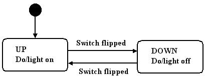
One could argue that our light switch really has hundreds of thousands or millions of states, since every time we flip the switch it wears out just a little bit, and eventually will fail if we flip it enough. However, in the world of state diagrams, we fortunately do not include this type of "event." We only include the states of the system when it is working in its normal course of operation. Although the actual number of possible events that could happen to any system (such as our light switch) approaches infinity (e.g., such as the switch being smashed by an asteroid hitting the earth), we do not include this type of event in the state diagram. (This is a good thing or all state diagrams would be so large as to be unreadable!) The only possible events that are shown on the state diagram are the ones the system is specifically built to handle and still keep working.
Example: simplistic Teaching Assistant (TA) :)
The states in a state diagram represent the states of being of the system. For example's sake, suppose that your TA only has two states of being: happy and sad. Further suppose that your TA is basically cheerful and starts out happy. :) Also suppose that your TA, not having much of a life, can only respond to two events: getting coffee (which makes the TA happy) and getting punched in the nose (which, needless to say, makes her sad).
Here is a state diagram that would represent our simplistic TA:
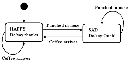
Note that although the TA need never get punched in the nose in her entire life--and we hope she doesn't!--we still need to include this event in our state diagram, just in case it happens. A state diagram must be able to represent any possible input sequence, not just input sequences that have already happened, or are likely to happen. As long as the event (such as getting punched in the nose) is an event the TA is built to recognize and respond to (by becoming sad and saying "Ouch!"), then we have to include it in her state diagram.
Also notice that some of the arrows in the TA's state diagram loop back to the state from which they came. That is, if the TA is already happy, and coffee is brought, she stays happy (and says "Thanks!"). If the TA is already sad, and gets punched in the nose again :(, she stays sad, and says, "Ouch."
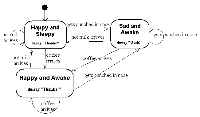
Here is a slightly more complex TA, with three states. This TA also responds to the arrival of hot milk, as well as to the arrival of coffee and to being punched in the nose. This TA starts out happy and sleepy, and only wakes up when coffee arrives, or by being punched in the nose. She also gets sleepy and happy again each time hot milk shows up.
Common Confusion #1:
While all state diagrams are similar in appearance, the systems represented by the different types of state diagrams can be fundamentally very different. When reading material on state diagrams on the Internet, do not get confused by the different types of state diagrams. There is one type of state diagram used with Finite State Machines (FSMs), which are theoretical constructs used in "Theory of Computation" work. We don't have time to go into details about FSMs here--there is plenty of material on the web if you are interested, and in books on the theory of computation-- but you should know that there is one striking practical difference between the theoretical FSMs and the real-world systems you are likely to be developing: FSMs have no memory or data store outside the knowledge represented by which state the FSM is currently in. That is, if you know the state of a FSM, you don't need to know any other data in order to know the exact future behavior of the FSM given any particular input sequence. For example, you won't find a state in an FSM described "Display the dynamic main menu, and wait for user to choose an item from the menu." Such a state requires that the current contents of the menu be stored someplace outside the context of the states themselves.
We will not be using the theoretical FSMs in this class, but instead will be dealing with practical real-world systems and with UML as a standard way of representing models of those real-world systems. These real-world systems can (and nearly always do, these days) have memory/knowledge/data stored outside the context of the states. This means that the functionality/behavior of a system while in a particular state can depend on information stored outside the states themselves. The dynamic menu system mentioned above is one example. One can think about the system being in the "state in which the system displays the dynamic menu then waits for user input." Yes, one could argue that (for example) all the different possible combinations of bits in the RAM, disk drives, registers, instruction pointers, and stack pointers are different possible states for the machine. However, the trillions of possibilities represented by all those bit combinations are not a really practical way to look at the PC-based system being built. In our dynamic menu example it is a lot easier to think of the system having one state in which it displays a changeable menu, rather than millions of states, each of which represents one possible menu that might be shown.
Be careful not to confuse the systems addressed in a class on system design and UML with those used in the study of Finite State Machines. It is perfectly fine, even advisable, to have states in your UML state diagrams whose internal functionality uses stored information.
Common Confusions #2: States vs. Events, or put another way in UML: Rounded Rectangles vs. Arrows.
In a state diagram, everything that might happen in the system or object being diagrammed happens *inside* the rounded rectangles that stand for the states; *all* possible events from the outside, including all input from the actors/users of the system, are represented as arrows from one state to another (or sometimes from one state looping back to itself).
NO possible action or event from outside the system ever gets placed inside a state. In UML state diagrams, that means NO action or event from outside the system (such as any action by a user) ever gets placed in a rounded rectangle. Instead, every possible action or event from outside the system is represented as an arrow with accompanying text, with the arrow running from one state to another, or from one state back to the same state.
Every arrow (except the arrow from the "Start" circle to the starting state) *must* be labeled with a possible event or action from outside the system. The arrow from the "Start" circle to the starting state does not have an event associated with it and gets no accompanying text.
So...every arrow except the start arrow is a possible event (such as a user action) from outside the system or object being diagrammed.
Every possible event is represented as an arrow with text describing the event.
No possible events from outside the system are inside a rounded rectangle.
No possible actions of the system or object being diagrammed are represented as an arrow. If the system does an action, that action should be represented as text inside a rounded rectangle that represents the state in which the system does that action.
[Note: There is an alternate method of presenting some system output, in which the output that a system emits when changing from one state to another is written on the arrow label after the input (event) that caused the state change, separated from the input description by a slash. For example, if receiving a "1" causes a system to output a "0" and change from state A to state B, the arrow from A to be might be labeled 1/0. If you use this method, do not confuse in any way the "0" that the system has output with the input "1" that caused the state change. Until you have the concept of "system activities in states, activities from outside the system on arrows" clearly in mind, be wary of this method of documenting system output in response to an input.]
All arrows must have text indicating for which event that arrow stands. If there is no event from outside the system, there is no arrow.
All states of being of the system or object being diagrammed are represented as rounded rectangles.
A Statistic from past terms in McCumber & Sloan's graduate course in Systems Development and Project Control: Nearly all students ended up asking for help on the state diagram assignment.
Those students who have not worked with state diagrams before may want to call their professor or teaching assistant for a private phone help session about state diagrams. Sometimes just a short conversation can make things a lot more clear!
Copyright © 1999-2006 EagleRidge Technologies, Inc.